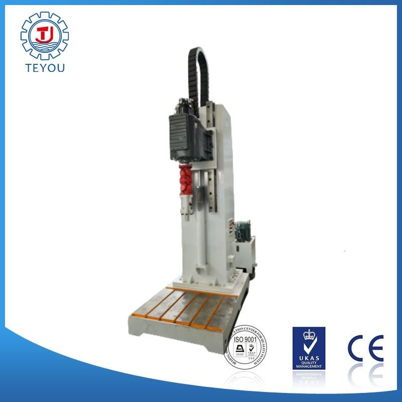
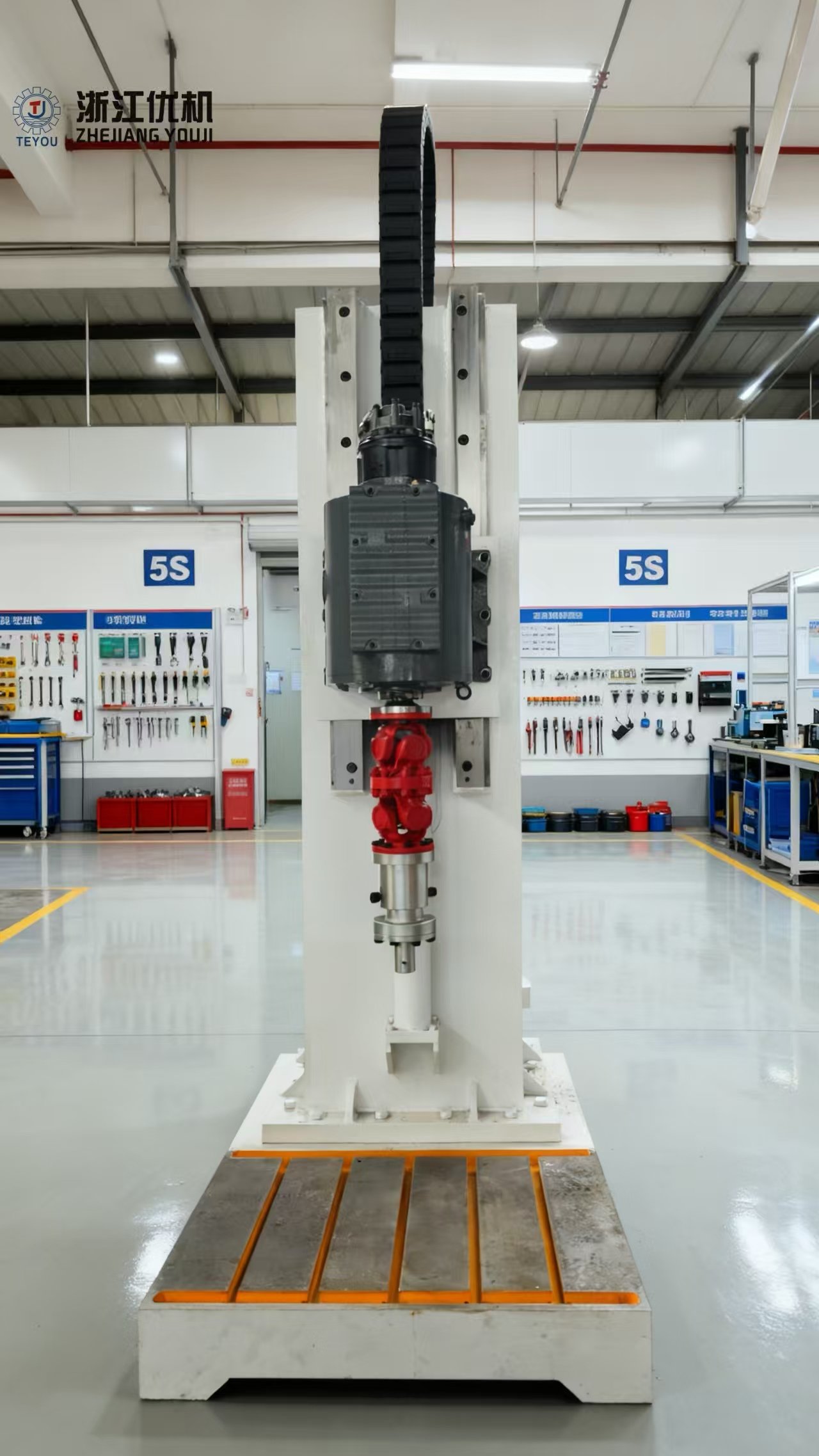
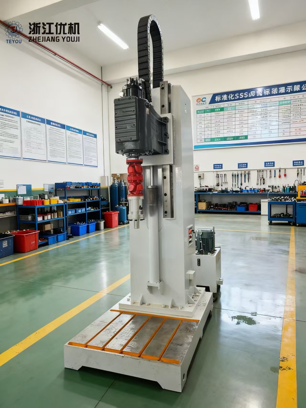
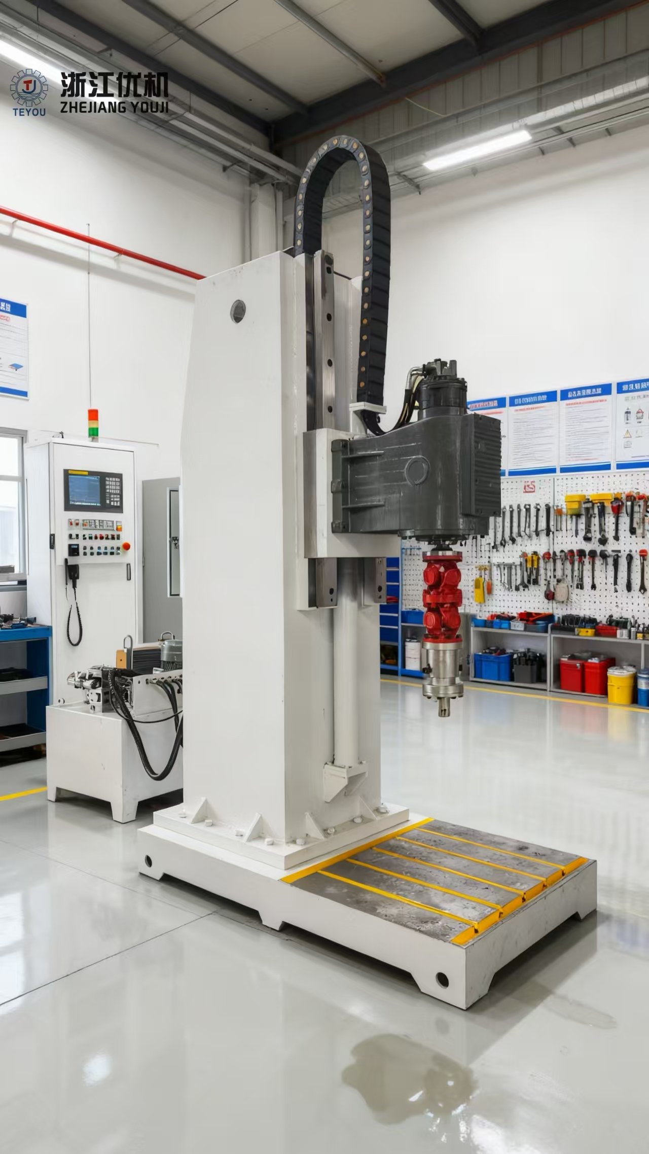
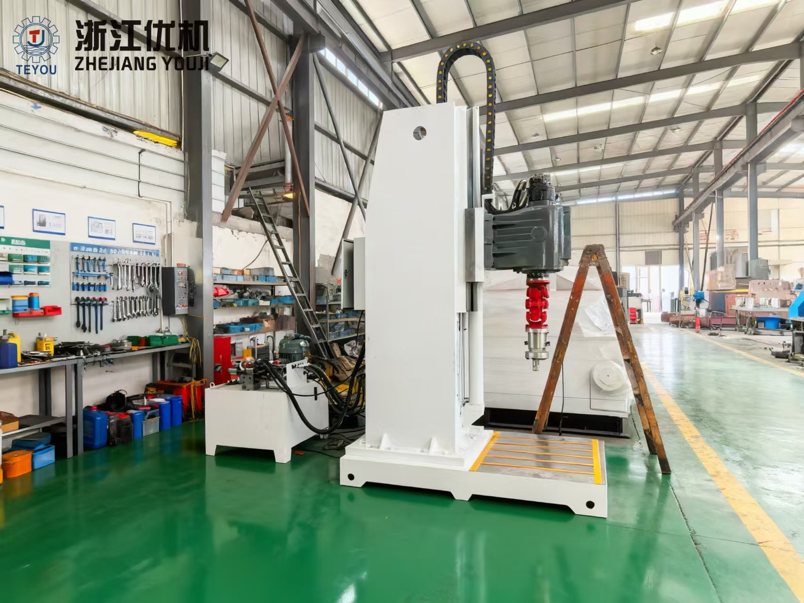
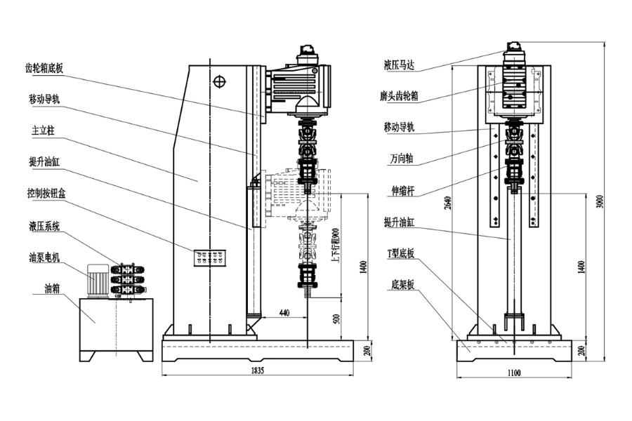
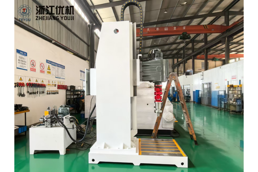
Built on precision lapping theory, the JLX-series plug valve seat lapping machine uses a gearbox drive with a hydraulic motor to achieve variable speed, forward and reverse rotation, and controlled vertical pulsing. The grinding head forms its motion path via a universal joint and telescopic rod. An oil cylinder raises and lowers the head; the valve body and plug are aligned through the universal joint, while contact pressure on the sealing faces is tuned by the telescopic rod. The machine integrates electromechanical, hydraulic, gearbox, and recirculating lubrication systems into a single unit for stable performance and a high degree of automation. It is designed for lapping plug valve sealing faces with nominal diameters DN200–DN400, delivering high surface finish and approximately 90% mating conformity.
Lapping System Operating Procedure
- Power on the hydraulic system. Manually secure the valve body to the T‑slot table and connect the lapping plug to the machine.
- Evenly apply lapping grit or compound to the valve body or the lapping plug.
- Lower the lapping plug with the lift cylinder and stop 5–10 mm above the sealing face.
- Start the hydraulic motor and reciprocating cylinder to drive combined vertical and rotary reciprocation of the plug.
- Continue lowering until, at the lowest point of the reciprocation stroke, the plug contacts the sealing face. Lapping begins.
IV. JLX‑400 Technical Specifications
| Item | Unit | Specification |
|---|---|---|
| Model | — | JLX‑400 |
| Applicable valve size | mm (in) | DN200–DN400 (8″–16″) |
| Opening span (vertical clearance) | mm | 500–1350 |
| Power supply | V / Hz | 380 V / 50 Hz |
| Hydraulic pump motor power | kW | 5.5 |
| Hydraulic motor rated torque | N·m | 760 |
| Hydraulic motor speed | r/min | 1–600 |
| Gearbox ratio | i | 6.48 |
| Gearbox rated torque | N·m | TN2 = 2000 |
| Gearbox output reciprocation distance | mm | 9 (6 non‑identical reciprocations per revolution) |
| Overall dimensions (L × W × H) | cm | 184 × 110 × 300 |
| Net weight | kg | 4100 |
- Single‑station lapping range: DN200–DN400
- Gearbox vertical reciprocation: 6–6.5 cycles per revolution
- Lift cylinder: thrust 0–8 t, stroke 0–900 mm
- Hydraulic motor oscillation angle: adjustable 90°–360°
- Universal coupling: nominal torque 8000 N·m, fatigue torque 4000 N·m, overall length 360, dual‑flange connection
V. Hydraulic System Features & Configuration
<aside> 💡
Auto unload circuit (new): The system automatically depressurizes in standby and restores pressure on command, effectively reducing oil temperature and power consumption, and extending the service life of the pump, motor, and sealing elements.
</aside>
- Pressure gauges: Hangzhou Huake, Leierda anti‑vibration gauges
- Solenoid valves: Shanghai Huada, ISO standard (Rexroth‑type)
- Seals: O‑rings by Taiwan Weltop; cylinder seals TPU by Bayer (Germany)
- Hydraulic manifold block: process ports locked with high‑pressure screws; pickling and nickel‑plating finish
- Gearbox: Zhejiang Youji Machinery Technology Co., Ltd.
- Pump motor: Wannan Motor
- Electrical: CHINT components; pushbuttons by Hongbo (Schneider‑type)
- Hydraulic motor: Ningbo Tailerms Hydraulic Co., Ltd.
- Universal joint: Wuxi Saiwei Machinery Co., Ltd.
- Air‑cooling unit for hydraulic system: oil tank temperature control
VI. Major Materials & Manufacturing
- Piston rod: 40Cr, quenched and tempered HRC 28–32, hard‑chrome plated surface
- Cylinder: cold‑drawn seamless steel tube
- Piston: wear‑resistant grey cast iron QT‑450
- Guideways: 42CrMo
- Cabinet uprights: welded Q235A
- T‑slot work plate: cast iron 355
- Main column: welded Q235
- Coating: eco water‑based paint, off‑white, three‑coat system (primer, anti‑rust, topcoat)
VII. Documentation Provided
- Packing list, certificate of conformity, and user manual (including hydraulic schematic, air/water piping schematic, operating instructions, and common troubleshooting), 1 set each
VIII. Site Installation & Operating Conditions
- Ambient temperature: 1–40 °C
- Relative humidity: ≤ 90% RH
- Environment: free from high dust and corrosive gases; non‑hazardous atmosphere; good ventilation
- Floor space: leave ≥ 1 m clearance on all sides for access and maintenance
- Foundation: level floor is sufficient
IX. On‑site Installation, Commissioning & Training
1) Preparation (by user)
- Provide suitable indoor area; place equipment and level the floor; reserve operating clearance
- Prepare hydraulic oil and power supply
2) Installation
- Indoor installation required
- Cable connections (user to provide incoming power and communication cables)
- Itemized checks before formal commissioning
3) Commissioning
- Electrical: power‑on and signal tests
- Mechanical motion tests
- Integrated clamping and valve‑body setup
4) Training
- System principles, workflow, and key components
- Operating procedures
- Daily maintenance and care
X. Additional Notes
- Supplier is responsible for commissioning, installation guidance, and free operator training
- 12‑month domestic warranty; lifetime paid service available thereafter
- Delivery documentation includes user manual, troubleshooting guide, electrical schematic, and hydraulic cylinder assembly drawing
- During detailed engineering and manufacturing, minor dimensional adjustments may occur
- Payment terms: 40% deposit, balance due before shipment
- Lubricant not included: gear oil L‑CKC‑320 to be supplied by user (shipping restrictions)
- Hydraulic oil not included: No. 46 anti‑wear hydraulic oil to be supplied by user (shipping restrictions)
- Standard lead time: 70 days
- Valve seal grinding equipment